RTOS: Difference between revisions
| Line 476: | Line 476: | ||
*We use IRAM_ATTR to have our ISR reside in Internal RAM rather than flash | *We use IRAM_ATTR to have our ISR reside in Internal RAM rather than flash | ||
*We use volatile to make sure the compiler does not optimize the updates out | *We use volatile to make sure the compiler does not optimize the updates out | ||
= | =Multicore= | ||
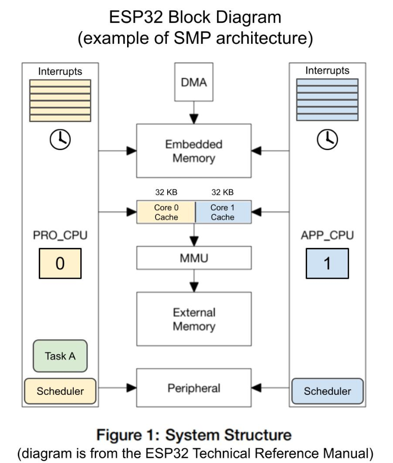
Quite liked the diagram describing the ESP32. I was interesting to note the idea of CPU_0 running wifi and bluetooth and CPU_1 for the apps.<br> | |||
< | [[File:Screenshot from 2024-12-30 17-36-23.png| 600px]]<br> | ||
. | |||
< | |||
Revision as of 04:39, 30 December 2024
Introduction
Thought I would do a page on RTOS so I have the terminology right. May do the same for Zephyr and Embassy to see how they compare.
RTOS Platforms
For me I have come across the different platforms
- Zephyr running on my Nordic boards
- FreeRTOS no used but the course drove me to this
- IDF RTOS running on my ESP32 (not sure the difference)
Arduino
I guess most people of familiar with the Arduino approach to software with sketches. I dislike the ecosystem and try to avoid it but this is what the course used.
void foo1() {
  // Do some function
}

void foo2() {
  // Do some function
}

void setup() {
  // Do some setup
}

void loop() {
  // Do something forever
  foo1();
  foo2();
}
Using Arduino with RTOS
The purpose of this page we will use only one processor, whereas the ESP32 I am using has two. To disable this we will use the following code. It will be omitted from code examples to save space.
// Use only core 1 for demo purposes
#if CONFIG_FREERTOS_UNICORE
static const BaseType_t app_cpu = 0;
#else
static const BaseType_t app_cpu = 1;
#endif
Tasks
In RTOS a task is a unit of work. It have these states
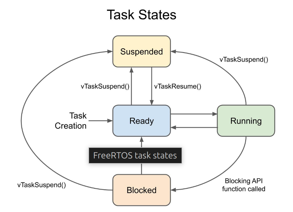
To create a task we use the following code.
 // Task to run forever
  xTaskCreatePinnedToCore(  // Use xTaskCreate() in vanilla FreeRTOS
              toggleLED_1,  // Function to be called
              "Toggle 1",   // Name of task
              1024,         // Stack size (bytes in ESP32, words in FreeRTOS)
              NULL,         // Parameter to pass to function
              1,            // Task priority (0 to configMAX_PRIORITIES - 1)
              NULL,         // Task handle
              app_cpu);     // Run on one core for demo purposes (ESP32 only)
I guess this is mainly self explanatory. There are other APIs to create a task. I have used xTaskCreate, but I think we are using this to ensure only on CPU is useda task
Scheduler
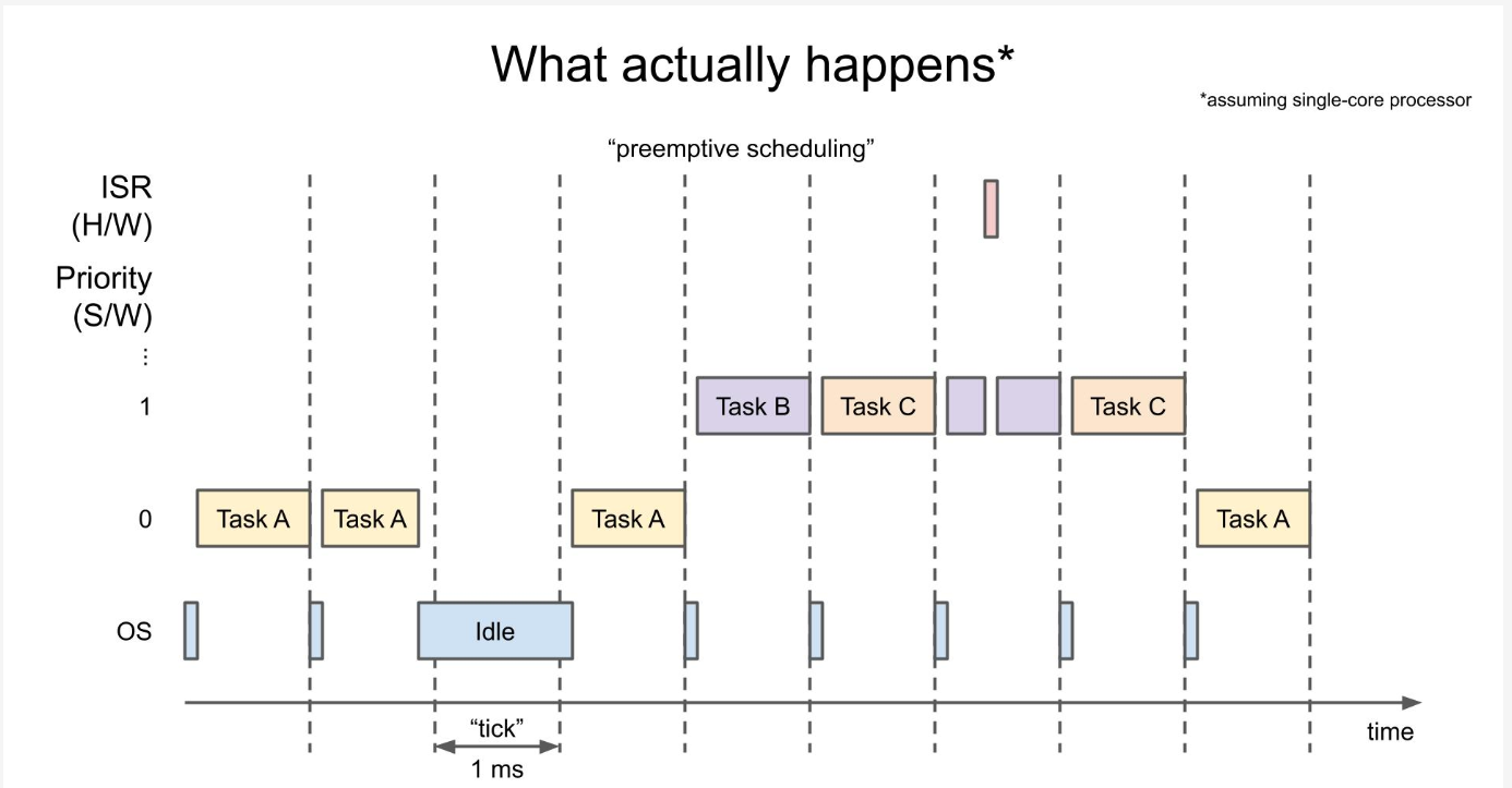
Clearly the most important part of the deal. This picture was provided with more information than my tiny brain could handle. I guess the salient points were.
- The default timeslice is 1 ms and known as a "tick"
- The hardware time is configure to create an interrupt every tick
- The and the ISR for the timer runs the scheduler
- This chooses which task to run
- The highest priority task is selected
- If there are two, then it uses round robin
- If a task with a higher priority becomes ready it is run immediately rather than wait for the scheduler
- A hardware interrupt is always considered to have a higher priority than any tasks
- You can change priority of a create task two.
Now the pretty picture. Where the pink is an ISR
Memory
Quite liked this picture, although do understand the difference between the heap and the stack, it is a nice picture to remind you.
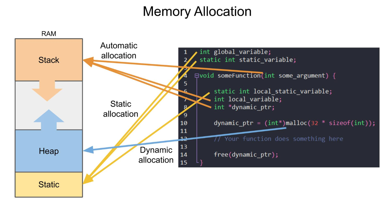
For RTOS this might be how the memory is allocated.
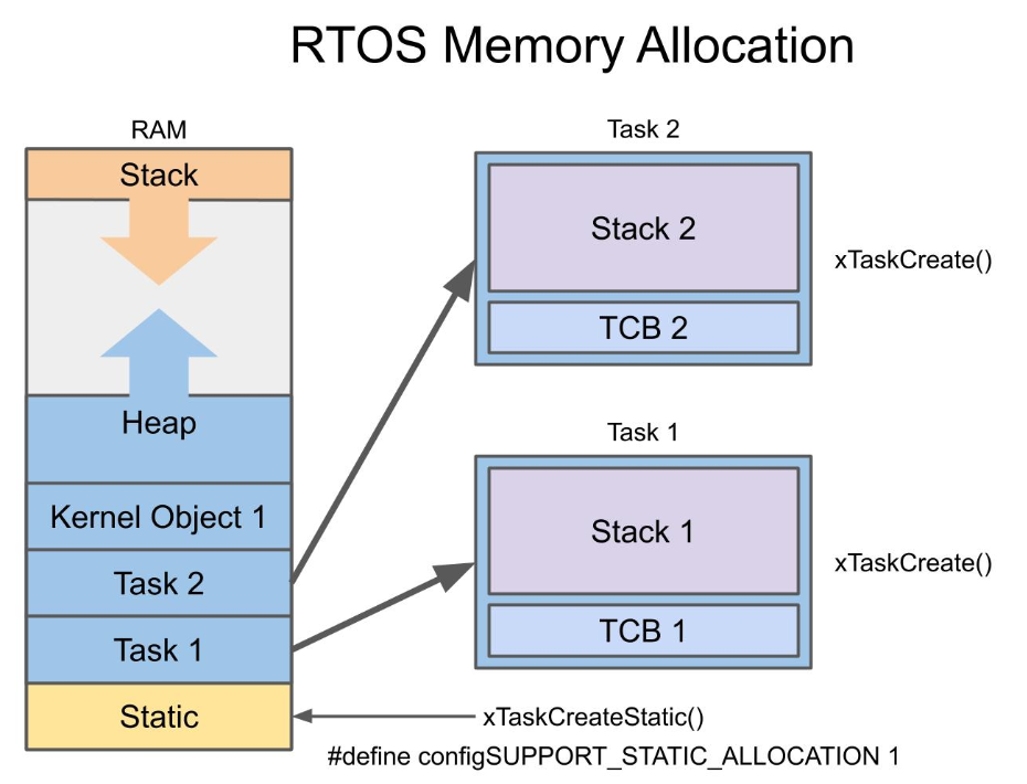
The task control block for a task holds properties about the task. e.g. Priority stack pointer. The kernel object like semaphores and queues also get allocated on the heap. There are different strategies for allocating memory in FreeRTOS depending on your needs. The demo showed mentioned
- use pvPortMalloc as it is thread safe
- you can use xPortGetFreeHeapSize() to get the amount free in bytes
- use pvPortFree to free the memory
Queues
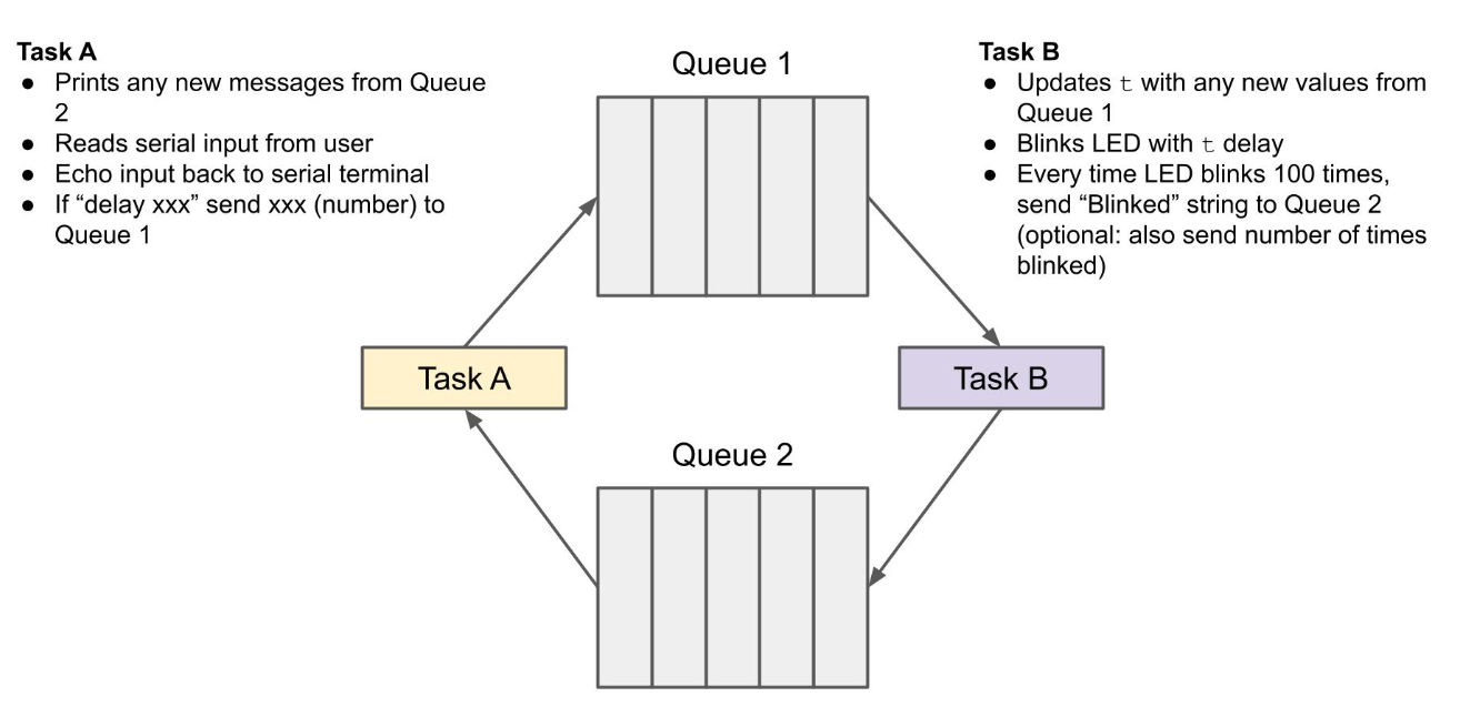
With all that theory time for some code. Queue can be a way to ensure data is passed to a process in the correct order. This is the pretty picture for the queues challenge
/**
 * Solution to 05 - Queue Challenge
 *
 * One task performs basic echo on Serial. If it sees "delay" followed by a
 * number, it sends the number (in a queue) to the second task. If it receives
 * a message in a second queue, it prints it to the console. The second task
 * blinks an LED. When it gets a message from the first queue (number), it
 * updates the blink delay to that number. Whenever the LED blinks 100 times,
 * the second task sends a message to the first task to be printed.
 *
 * Date: January 18, 2021
 * Author: Shawn Hymel
 * License: 0BSD
 */

// Use only core 1 for demo purposes
#if CONFIG_FREERTOS_UNICORE
  static const BaseType_t app_cpu = 0;
#else
  static const BaseType_t app_cpu = 1;
#endif

// Settings
static const uint8_t buf_len = 255;     // Size of buffer to look for command
static const char command[] = "delay "; // Note the space!
static const int delay_queue_len = 5;   // Size of delay_queue
static const int msg_queue_len = 5;     // Size of msg_queue
static const uint8_t blink_max = 100;   // Num times to blink before message

static const int LED_BUILTIN = 23;

// Pins (change this if your Arduino board does not have LED_BUILTIN defined)
static const int led_pin = LED_BUILTIN;

// Message struct: used to wrap strings (not necessary, but it's useful to see
// how to use structs here)
typedef struct Message {
  char body[20];
  int count;
} Message;

// Globals
static QueueHandle_t delay_queue;
static QueueHandle_t msg_queue;

//*****************************************************************************
// Tasks

// Task: command line interface (CLI)
void doCLI(void *parameters) {

  Message rcv_msg;
  char c;
  char buf[buf_len];
  uint8_t idx = 0;
  uint8_t cmd_len = strlen(command);
  int led_delay;

  // Clear whole buffer
  memset(buf, 0, buf_len);

  // Loop forever
  while (1) {

    // See if there's a message in the queue (do not block)
    if (xQueueReceive(msg_queue, (void *)&rcv_msg, 0) == pdTRUE) {
      Serial.print(rcv_msg.body);
      Serial.println(rcv_msg.count);
    }

    // Read characters from serial
    if (Serial.available() > 0) {
      c = Serial.read();

      // Store received character to buffer if not over buffer limit
      if (idx < buf_len - 1) {
        buf[idx] = c;
        idx++;
      }

      // Print newline and check input on 'enter'
      if ((c == '\n') || (c == '\r')) {

        // Print newline to terminal
        Serial.print("\r\n");

        // Check if the first 6 characters are "delay "
        if (memcmp(buf, command, cmd_len) == 0) {

          // Convert last part to positive integer (negative int crashes)
          char* tail = buf + cmd_len;
          led_delay = atoi(tail);
          led_delay = abs(led_delay);

          // Send integer to other task via queue
          if (xQueueSend(delay_queue, (void *)&led_delay, 10) != pdTRUE) {
            Serial.println("ERROR: Could not put item on delay queue.");
          }
        }

        // Reset receive buffer and index counter
        memset(buf, 0, buf_len);
        idx = 0;

      // Otherwise, echo character back to serial terminal
      } else {
        Serial.print(c);
      }
    }
  }
}

// Task: flash LED based on delay provided, notify other task every 100 blinks
void blinkLED(void *parameters) {

  Message msg;
  int led_delay = 500;
  uint8_t counter = 0;

  // Set up pin
  pinMode(LED_BUILTIN, OUTPUT);

  // Loop forever
  while (1) {

    // See if there's a message in the queue (do not block)
    if (xQueueReceive(delay_queue, (void *)&led_delay, 0) == pdTRUE) {

      // Best practice: use only one task to manage serial comms
      strcpy(msg.body, "Message received ");
      msg.count = 1;
      xQueueSend(msg_queue, (void *)&msg, 10);
    }

    // Blink
    digitalWrite(led_pin, HIGH);
    vTaskDelay(led_delay / portTICK_PERIOD_MS);
    digitalWrite(led_pin, LOW);
    vTaskDelay(led_delay / portTICK_PERIOD_MS);

    // If we've blinked 100 times, send a message to the other task
    counter++;
    if (counter >= blink_max) {

      // Construct message and send
      strcpy(msg.body, "Blinked: ");
      msg.count = counter;
      xQueueSend(msg_queue, (void *)&msg, 10);

      // Reset counter
      counter = 0;
    }
  }
}

//*****************************************************************************
// Main (runs as its own task with priority 1 on core 1)

void setup() {

  // Configure Serial
  Serial.begin(115200);

  // Wait a moment to start (so we don't miss Serial output)
  vTaskDelay(1000 / portTICK_PERIOD_MS);
  Serial.println();
  Serial.println("---FreeRTOS Queue Solution---");
  Serial.println("Enter the command 'delay xxx' where xxx is your desired ");
  Serial.println("LED blink delay time in milliseconds");

  // Create queues
  delay_queue = xQueueCreate(delay_queue_len, sizeof(int));
  msg_queue = xQueueCreate(msg_queue_len, sizeof(Message));

  // Start CLI task
  xTaskCreatePinnedToCore(doCLI,
                          "CLI",
                          1024, // Will crash change to 2024
                          NULL,
                          1,
                          NULL,
                          app_cpu);

  // Start blink task
  xTaskCreatePinnedToCore(blinkLED,
                          "Blink LED",
                          1024,
                          NULL,
                          1,
                          NULL,
                          app_cpu);

  // Delete "setup and loop" task
  vTaskDelete(NULL);
}

void loop() {
  // Execution should never get here
}
Doing this course made it very much easier to fix. The ESP32 crashes with

The line "Stack canary watchpoint triggered" points to the task with a problem. In our case it was the CLI task. We can debug this with Serial.println statements but the reason it failed was not a large enough stack size. I would not have guessed this before the course.
Mutexes
familiar ground with some terms to remember.
- critical section is a segment of code that needs to be executed as a single unit without interruption
- Mutual exclusion (mutex) is a technique that prevents multiple threads from accessing a shared resource at the same time
So no surprises there. Note the API is xSemaphore but these are mutexes. For FreeRTOS there are several APIs to do this depending on you situation but here are the main ones.
// Create a mutex
xSemaphoreCreateMutex()

// Take the mutex
// It will wait until mutex available for portMAX_DELAY and return false if not
xSemaphoreTake(mutex, portMAX_DELAY);

// Start Critical Code here
...
// End Critical Code here

// Release the mutex so that the creating function can finish
xSemaphoreGive(mutex);
Priority Inheritance
When a higher-priority thread tries to lock a mutex that is currently held by a lower-priority thread, the higher-priority thread blocks while the mutex owner's priority is temporarily raised to match the higher-priority thread. This ensures that the higher-priority thread is blocked for the shortest amount of time possible.
Semaphores
So semaphores allow more than one resource access it. Each time a producer/consumer accesses the resource the number is incremented. You still have all of the problems with updating if you use semaphores for the resource. In the example in just matters that the consumers get the event
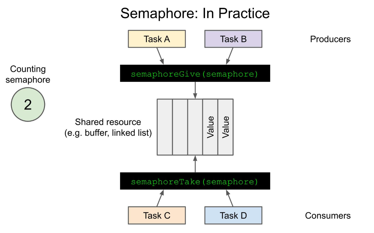
Therefore they are typically used in a producer/consumer.
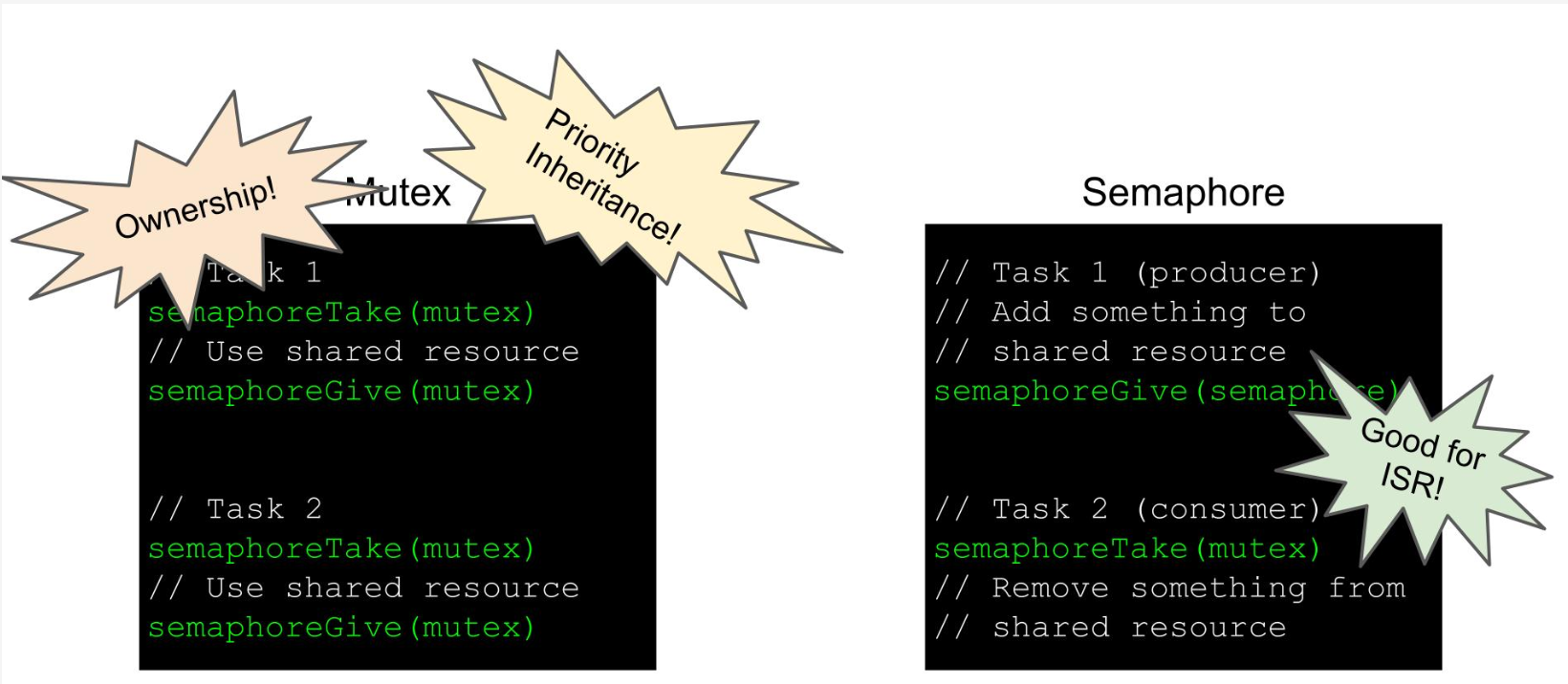
You can make a binary semaphore only counts to 1. Here is why it is different from a mutex. With a binary semaphore, there are two parties involved, a provider and consumer.
Software Timers
FreeRTOS provides APIs for creating timers. Much like tasks, you give them a name and there are some special functions for ISRs. Below is how to create a one shot timer. The Auto-Reload parameter determines if the timer is run once.
  one_shot_timer = xTimerCreate(
                      "One-shot timer",     // Name of timer
                      dim_delay,            // Period of timer (in ticks)
                      pdFALSE,              // Auto-reload
                      (void *)0,            // Timer ID
                      autoDimmerCallback);  // Callback function
Here is an example of echoing things back to serial port, turning on the LED when while entering input and keeping it on for n ticks. Restart can be issued to timers already running.
void doCLI(void *parameters) {

  char c;

  // Configure LED pin
  pinMode(led_pin, OUTPUT);

  while (1) {

    // See if there are things in the input serial buffer
    if (Serial.available() > 0) {

      // If so, echo everything back to the serial port
      c = Serial.read();
      Serial.print(c);

      // Turn on the LED
      digitalWrite(led_pin, HIGH);

      // Start timer (if timer is already running, this will act as
      // xTimerReset() instead)
      xTimerStart(one_shot_timer, portMAX_DELAY);
    }
  }
}
Hardware Timers
Well some terminology to remember in this bit. The terms prescaler and count were used. If we had an 80 Mhz clock this would count 80 million times. The prescaler is the amount to scale the timer by. E.g. a value of 80 would mean the clocking would now count 1 million times. The counter is the thing that holds the current count. It is important to ensure it is large enough to hold the max value after prescaling
Interrupt Service Routines
Used to these on an STM32. Here is the code which and lots to take away below.
 #define LED_BUILTIN 23

#if CONFIG_FREERTOS_UNICORE
  static const BaseType_t app_cpu = 0;
#else
  static const BaseType_t app_cpu = 1;
#endif

// Settings
static const uint16_t timer_divider = 8;
static const uint64_t timer_max_count = 1000000;
static const TickType_t task_delay = 2000 / portTICK_PERIOD_MS;

// Globals
static hw_timer_t *timer = NULL;
static volatile int isr_counter;
static portMUX_TYPE spinlock = portMUX_INITIALIZER_UNLOCKED;

//*****************************************************************************
// Interrupt Service Routines (ISRs)

// This function executes when timer reaches max (and resets)
void IRAM_ATTR onTimer() {

  // ESP-IDF version of a critical section (in an ISR)
  portENTER_CRITICAL_ISR(&spinlock);
  isr_counter++;
  portEXIT_CRITICAL_ISR(&spinlock);

  // Vanilla FreeRTOS version of a critical section (in an ISR)
  //UBaseType_t saved_int_status;
  //saved_int_status = taskENTER_CRITICAL_FROM_ISR();
  //isr_counter++;
  //taskEXIT_CRITICAL_FROM_ISR(saved_int_status);
}

//*****************************************************************************
// Tasks

// Wait for semaphore and print out ADC value when received
void printValues(void *parameters) {

  // Loop forever
  while (1) {

    // Count down and print out counter value
    while (isr_counter > 0) {

      // Print value of counter
      Serial.println(isr_counter);

      // ESP-IDF version of a critical section (in a task)
      portENTER_CRITICAL(&spinlock);
      isr_counter--;
      portEXIT_CRITICAL(&spinlock);

      // Vanilla FreeRTOS version of a critical section (in a task)
      //taskENTER_CRITICAL();
      //isr_counter--;
      //taskEXIT_CRITICAL();
    }

    // Wait 2 seconds while ISR increments counter a few times
    vTaskDelay(task_delay);
  }
}

//*****************************************************************************
// Main (runs as its own task with priority 1 on core 1)

void setup() {

  // Configure Serial
  Serial.begin(115200);

  // Wait a moment to start (so we don't miss Serial output)
  vTaskDelay(1000 / portTICK_PERIOD_MS);
  Serial.println();
  Serial.println("---FreeRTOS ISR Critical Section Demo---");

  // Start task to print out results
  xTaskCreatePinnedToCore(printValues,
                          "Print values",
                          1024,
                          NULL,
                          1,
                          NULL,
                          app_cpu);

  // Create and start timer (num, divider, countUp)
  // const uint32_t frequency = 80000000 / timer_divider;
  timer = timerBegin(10000000); // 10 Mhz
  // timer = timerBegin(0, timer_divider, true);

  // Provide ISR to timer (timer, function, edge)
  timerAttachInterrupt(timer, &onTimer);
  // timerAttachInterrupt(timer, &onTimer, true);

  // At what count should ISR trigger (timer, count, autoreload)
  // timerAlarmWrite(timer, timer_max_count, true);
  timerAlarm(timer, timer_max_count, true, 0);

  // Allow ISR to trigger
  // timerStart(timer);

  // Delete "setup and loop" task
  vTaskDelete(NULL);
}

void loop() {
  // Execution should never get here
}
This code has a task prints values and decrements the global variable and an ISR which runs every 1 second onTimer which increments a global variable.
- The API's for FreeRTOS are slighty different from IDF
- The divider, prescaler are not support on my RTOS
- We use spinlocks to disable other ISRs
- We use IRAM_ATTR to have our ISR reside in Internal RAM rather than flash
- We use volatile to make sure the compiler does not optimize the updates out
Multicore
Quite liked the diagram describing the ESP32. I was interesting to note the idea of CPU_0 running wifi and bluetooth and CPU_1 for the apps.
